Acoustics and Vibration Animations

Daniel A. Russell, Graduate Program in Acoustics, The Pennsylvania State University

Creative Commons License
This work by Dan Russell is licensed under a Creative Commons Attribution-NonCommercial-NoDerivatives 4.0 International License.
Based on a work at http://www.acs.psu.edu/drussell/demos.html.

The content of this page was originally posted on October 8, 2011. The HTML code was modified to be HTML5 compliant on March 16, 2013.


Reflection from an Impedance Discontinuity and the Standing Wave Ratio

In my webpage Superposition of Waves I show that when two waves travel in the same medium at the same time, their amplitudes add together linearly so that the resulting wave is just the sum of the two individual waves. In the animation Reflections of Waves From Boundaries I showed animations illustrating what happens when a wave pulse reflects from a soft boundary, a hard boundary, as well as showing how a wave is partially reflected and transmitted across a boundary into a different medium. That animation illustrated the phenomena of superposition using wave pulses. For the animations below I wanted to explore what happens when a continuous wave train encounters a change in the medium and reflects to create standing waves.

The Incident Wave Train

animation showing wave train traveling to the right

A wave train is just a long sinusoidal wave that may have a beginning (or end) but which is long enough that once the front of the wave has passed by, the wave just looks like an infinitely long sinusoidal wave function. The animation at left shows such a sinusoidal wave train traveling toward the right. I've shown the wave passing through a "boundary" without any change in the amplitude or phase of the wave. This is what we would expect to see for a wave encountering a second medium that has exactly the same characteristic mechanical impedance as the first medium. The characteristic mechanical impedance is the square root of the product of the elastic modulus and the mass density of the medium. Even though the materials might be different, as long as the characteristic impedances are the same, the wave train will pass directly from the first medium into the second medium without any change.

Standing Waves (superposition of two waves traveling in opposite directions)

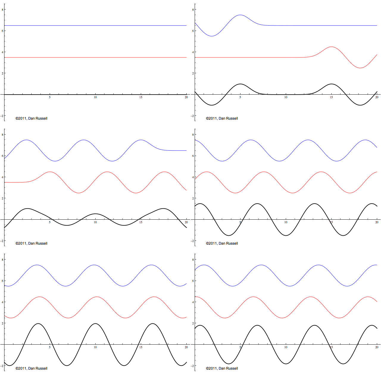
animation showng standing wave resulting from two oppositely directed sine waves

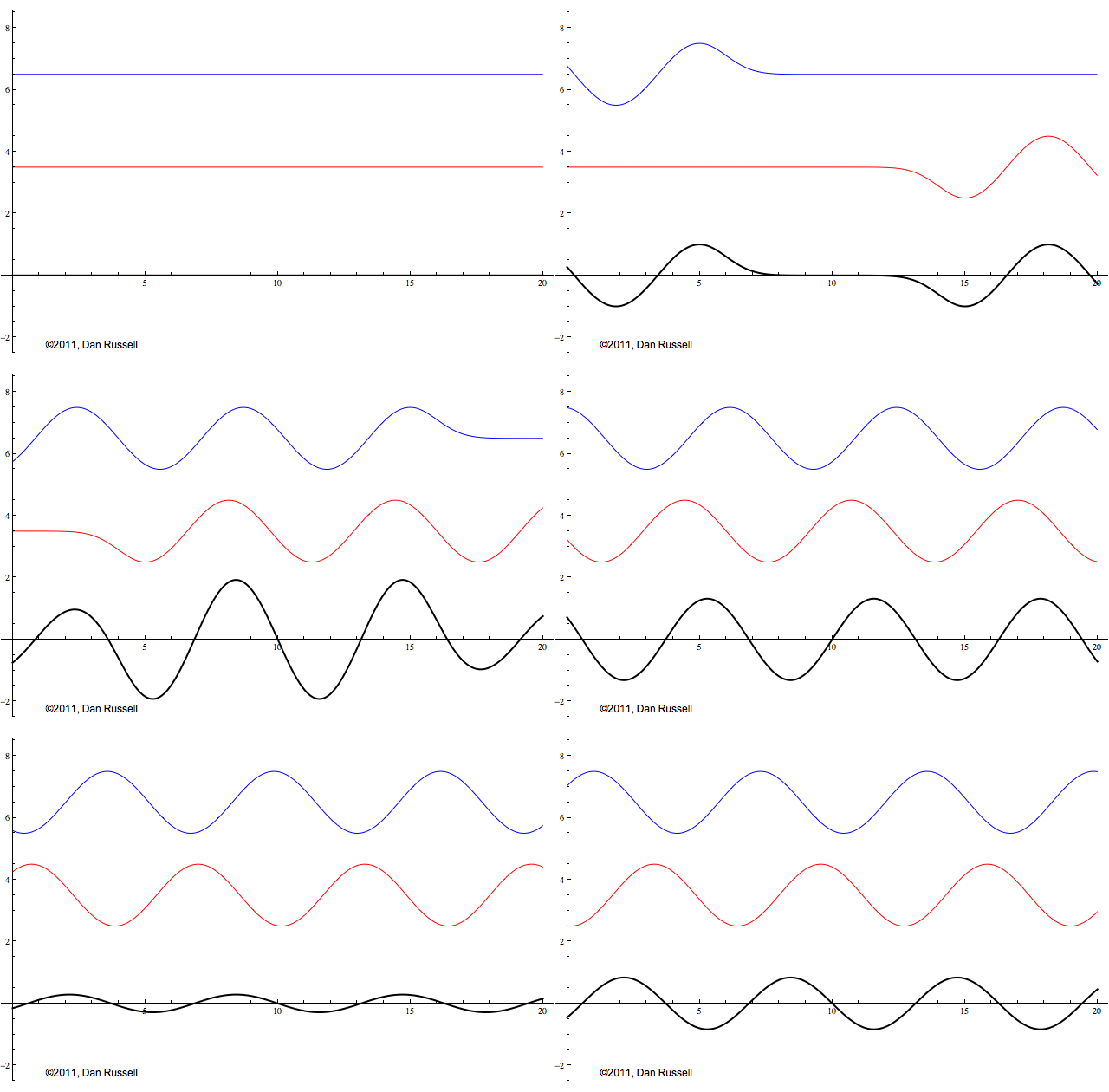
A traveling wave represents a disturbance that moves from one location to another location at a speed which depends on the elastic and inertia properties of the medium. The animation at left shows two traveling waves: the blue wave is traveling to the right and the red wave is traveling to the left. Both waves have the same amplitude, the same frequency, and the same wavelength.

The black signal in the animation represents the superposition of these two oppositely directed traveling waves. As these waves pass through each other and add together, they create a standing wave - a pattern which neither moves left or right, but simply oscillates up and down as a function of time. The amplitude of this standing wave is twice that of the individual waves when the two waves are in phase so that peaks and valleys line up. The amplitude of the standing wave is zero when the two waves are completely opposite phase so that they peaks of one wave line up with the valleys of the other wave; the two wave amplitudes cancel each other out.

animation showing standing wave resulting from two oppositely directed waves with inverted phase

This animation is almost the same as the one above, except that the red left-going wave is now upside down. This changes the initial shape of the combined sum wave as the two waves begin to pass through each other, but after a short time, the standing wave looks exactly the same. The bottom line is that whenever two waves with the same amplitude and the same frequency are traveling in opposite directions in the same medium, the result is a standing wave.

A traveling wave carries energy and momentum with it as it travels; for a traveling wave the kinetic and potential energy both travel with the wave and have the same value at a specific position at a specific time. In a traveling wave, the potential and kinetic energy do not trade back and forth like they do for oscillation. However, a standing wave (which results from two waves traveling in opposite directions) does not involve the propagation of energy. The energy in a standing wave is trapped between the nodes, and simply trades back and forth between kinetic and potential forms.

Standing Waves Due To Reflections from Hard and Soft Boundaries

animation of wave train reflecting from soft boundary to create standing wave

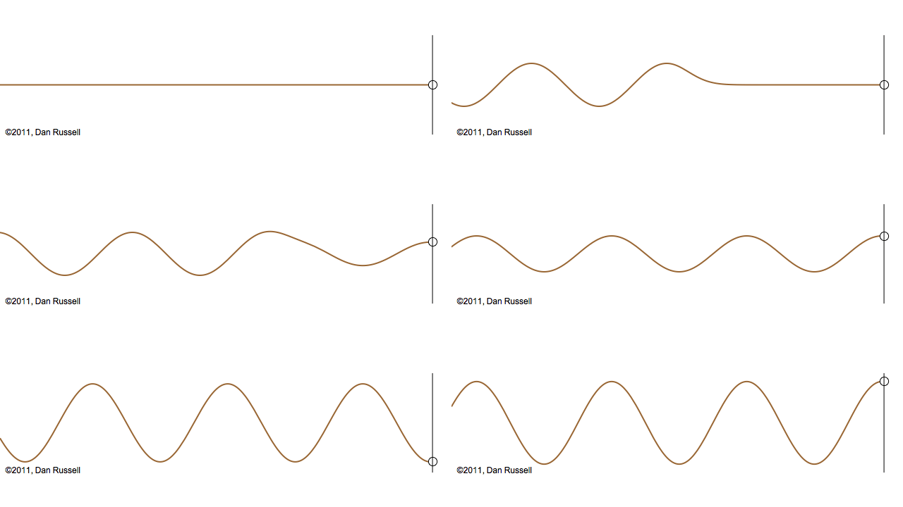
One way to get two waves traveling in opposite directions is to have a single wave train reflect from a boundary. The animation at left shows a wave train moving toward the right, incident upon a free boundary. A free boundary means that there is no force to limit the displacement. Mathematically, this results in the string having zero slope at the boundary. As was the case for a wave pulse reflection from a free end, the reflected wave has the same upright orientation as the incident wave, but is now traveling in the opposite direction.

As the incident wave train is reflected from the free end, a standing wave is quickly formed as the right-going incident wave is superposed with the left-going, upright reflected wave. The standing wave neither moves right or left, but simply oscillates up and down. Points on the string that do not move (where the amplitude is zero) are called nodes. Locations where the standing wave pattern has a maximum amplitude are called anti-nodes.

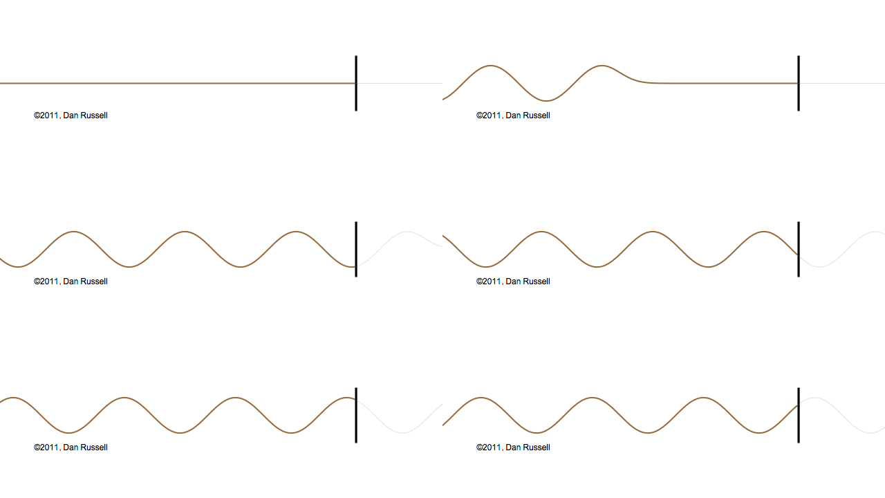
animation of wave train reflecting from hard boundary to create standing wave

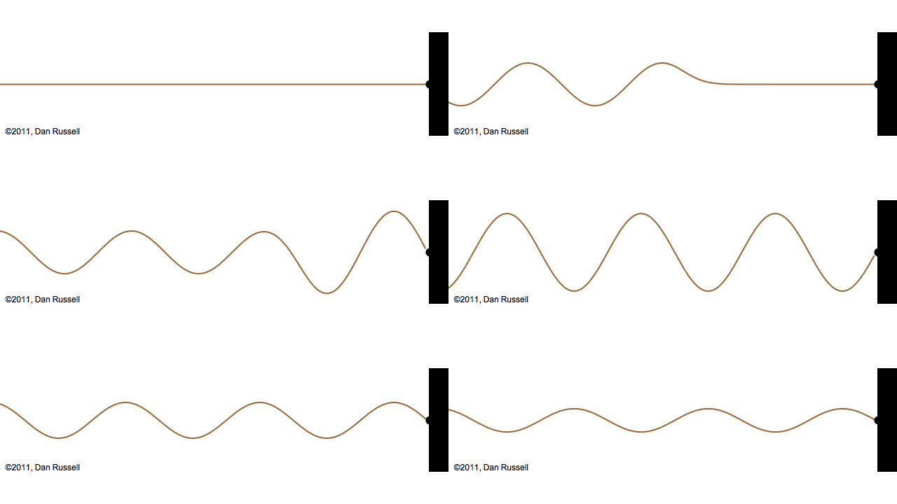
This animation shows how a wave train reflects from a hard, rigid boundary to form a standing wave. Just as we saw for a wave pulse reflection from a fixed end, the reflected wave is inverted (upside down) compared to the incident wave, and is now traveling in the opposite direction.

As the reflected wave superposes with the incident wave, a standing wave is quickly formed. There is no net transfer of energy The fixed end of the string is a node.

Reflection from an Impedance Discontinuity: the Standing Wave Ratio

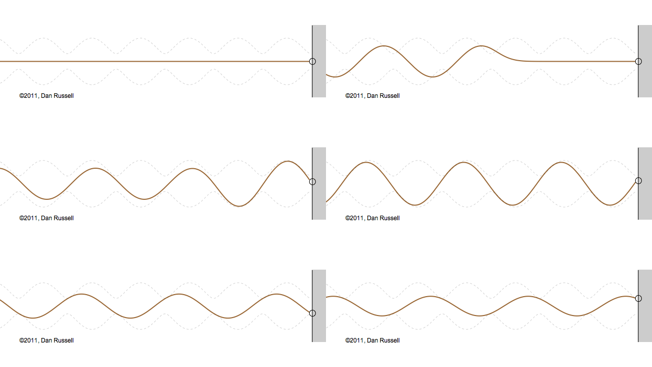
animation of wave train reflecting from impedance discontinuity
animation of wave train reflecting from impedance discontinuity showing outline of the standing wave ratio amplitude

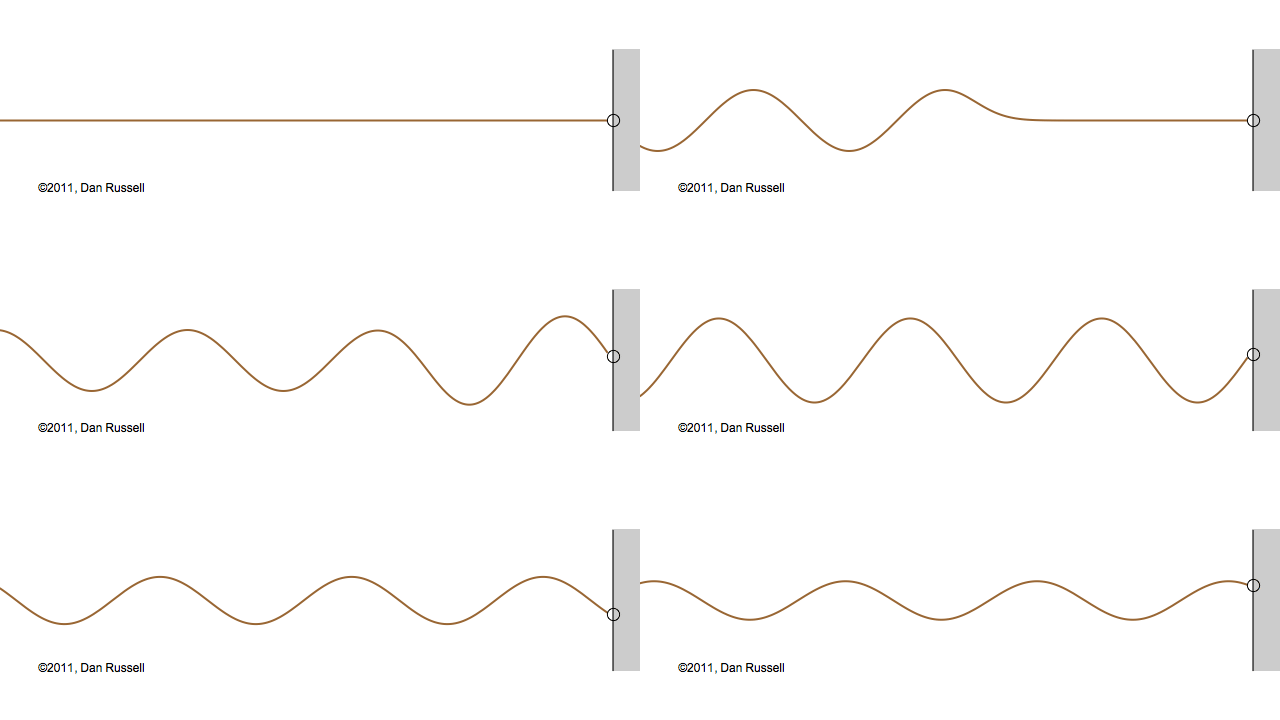
Now let's see what happens when an incident wave train encounters a boundary with an impedance that is somewhere between hard and soft. Now, only part of the incident wave is reflected; the rest is either absorbed by or transmitted into the second medium with the different impedance. The orientation of the reflected wave (whether upright or inverted) depends on whether the new material has a larger or smaller impedance. For this particular animation, the reflected wave has half of the amplitude of the incident wave, and is inverted.

The resulting superposition looks kind of like a standing wave, but it doesn't stay still. It appears to lurch forward toward the right. This should make sense since only a part of the energy carried by the original wave is reflected from the boundary; the rest of the incident energy is either absorbed by the impedance termination or transmitted into the second medium. As a result there is more energy moving to the right than there is being reflected to the left. There is a net energy flow to the right.

If you watch the above animation very carefully you will notice that the locations where the wave pattern reaches a maximum value are fixed in space. Likewise, the locations where the wave pattern has a minimum value are also fixed locations. So, while there is a net transfer of energy toward the right, there is an aspect of this wave pattern that does not change with time or space.

Mathematically, we can write the sum of the incident and reflected waves as,

$$ \xi(x,t)=\xi_o \sin(\omega t - kx) + \Gamma \xi_o \sin(\omega t + kx) $$

If we apply some trigonometric identities, we can show that the amplitude of this "pseudo-standing wave" depends on position according to

$$ C(x)=\sqrt{1 + \Gamma^2 + 2\Gamma \cos(2kx)} $$

The dashed curves in the animation at left represent the envelope defined by \(C(x)\), and you can see that as the "standing" wave is set up, it remains "fixed" within the confines of this envelope. The ratio of the maximum amplitude divided by the minimum amplitude is called the Standing Wave Ratio (SWR) and depends on the relative amount, \(\Gamma\), of the incident wave that is reflected from the boundary.

$$ \hbox{SWR}={\hbox{maximum amplitude} \over \hbox{minimum ampliutde}} = {1 + \Gamma \over 1 - \Gamma} $$

The standing wave ratio may be used to measure the value of the mechanical impedance and/or the absorption coefficient of an unknown material.

References

  1. The animations on this page were inspired by questions raised by graduate students in my ACS 501 Fundamentals of Acoustics course, after I assigned them problem 6.5 from the textbook by Akira Hirose and Karl E. Lonngren, Fundamentals of Wave Phenomena 2nd Ed., (SciTech Publishing, Raleigh, NC, 2010).

  2. During the 16 years (1995-2011) while I was a physics professor at Kettering University (GMI Engineering & Management Institute), I wrote a laboratory experiment (around 1997) to teach studnets how to measure Absorption Coefficients and Impedance of various acoustic materials using a B&K Standing Wave Apparatus Type 4002. In this experiment, students measured the standing wave ratio resulting from a sound wave reflecting from an unknown material, at various frequencies, and used the measured SWR to calculate the reflection coefficient, the impedance of the material (by hand and using a Smith Chart), and the sound power absorption coefficient.